1. Validate Studio
-
[Simulation Models Configurations](#simulation models-configurations)
[Simulation Models](#simulation models)
1.1. Introduction to Validate Studio
Welcome to Validate Studio, the premiere software-defined rigging tool that streamlines the intricate process of vehicle systems testing. With Validate Studio, engineering professionals can configure electronic control units and CAN networks with precision and ease.
Validate Studio is a part of the SODA.Auto ecosystem, which is a comprehensive suite of tools for automotive software development and testing. It is designed to be used in conjunction with other SODA.Auto V Suite tools, such as SODA.Sim and SODA.Create.
This powerful platform is adept at managing intricate vehicle configurations, as demonstrated by the robust demo setup. It supports comprehensive release management, integrates simulation model configurations, and maintains meticulous records of test executions. Embrace the efficiency of Validate Studio and elevate the testing and validation of your automotive projects.
1.2. Getting Started with Validate Studio
1.2.1. System Requirements
Ensure your client system meets the following minimal specifications for a smooth experience:
modern operating system (such as Windows 10),
4GB+ RAM recommended,
1GB of disk space or more,
modern web browser (such as Google Chrome, Mozilla Firefox, or Microsoft Edge).
For server installation, refer to the SODA.Auto development team for the necessary hardware and software requirements.
1.2.3. Initial Setup
For setting up new configuration, navigate to appropriate menu item and use the “+ Create…” option to add a new vehicle, test set or other items.
1.2.4. Installation
Refer to SODA.Auto development team to Install Validate Studio in desired configuration or run on-site demos.
1.3. Dashboard
The primary interface of Validate Studio is accessible through the specified URL.
Upon entering, click the primary navigation pane with “SODA Validate” logo.

The ensuing menu consists of the following segments of Validate Studio:
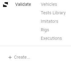
The following sections are available for configuration and management of the vehicle testing process:
[Simulation Models](#simulation models)
This interface is crafted for a seamless and user-friendly experience in vehicle systems testing and simulation for users of varying expertise.
1.4. Vehicles
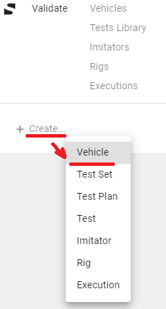
To add a new vehicle in Validate Studio, select the “+ Create…” option from the main navigation menu.
Then, choose “Vehicle” from the drop-down list to initiate the vehicle creation process.
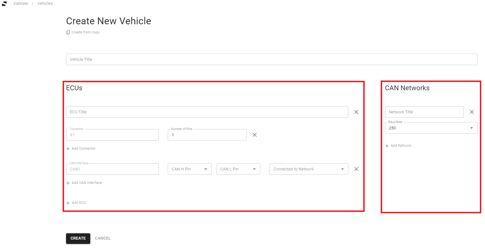
In the vehicle configuration interface, detail the electronic control units (ECUs) by providing their titles and specify the number of connectors and pins.
Subsequently, define the Controller Area Network (CAN) by listing each network along with its corresponding attributes, such as baud rate and associated ECUs.
Finalize your vehicle setup by linking the ECUs with the appropriate CAN networks, ensuring the configuration reflects the actual vehicle network architecture.
1.4.1. Adding ECUs
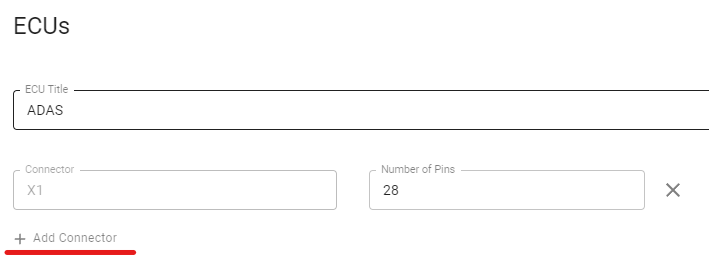
When adding an Electronic Control Unit (ECU) in Validate Studio, give the ECU a name without spaces to allow for easy reference in tests. Specify the number of connectors and the number of pins in each connector.
If you need more connectors, click the “+ Add Connector” button. Define which pins are linked to the High and Low lines of the CAN network.
Specify which pins are connected to the High and Low lines of the CAN network accordingly:
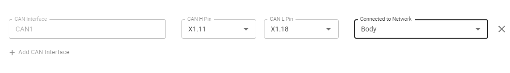
If your ECU links to more than one CAN network, add additional CAN interfaces by clicking the corresponding button.

To include another ECU, simply select the “+ Add ECU” button.

1.4.2. Adding CAN Networks
To add Controller Area Network (CAN) systems in Validate Studio:
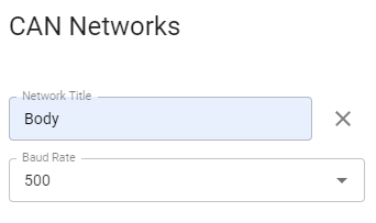
Choose a name for your CAN without spaces to enable straightforward referencing in tests. Set the baud rate from the options provided: 250, 500, or 1000 kilobits per second.
To insert additional CAN networks, use the “+ Add Network” button.

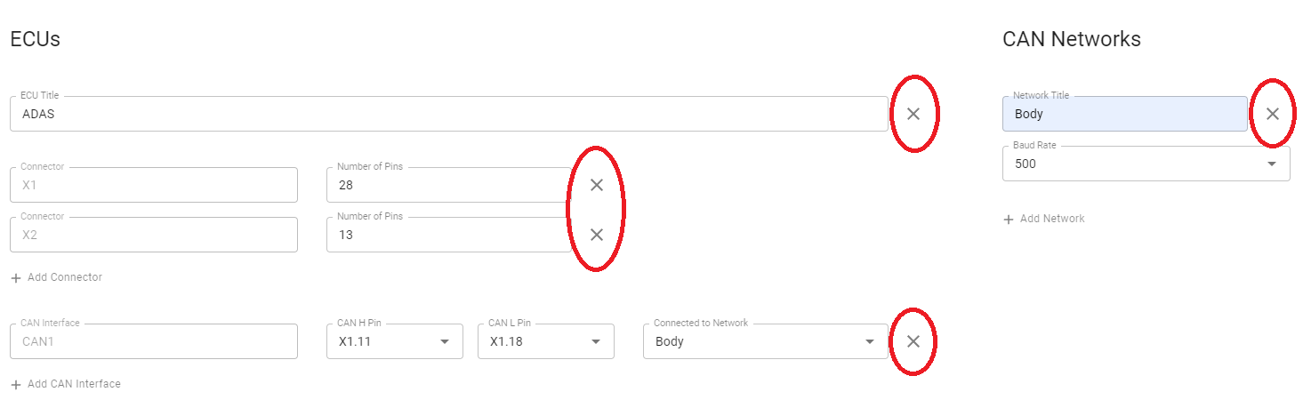
Remove any part of the configuration by selecting the cross button next to the item.
After defining all ECUs and CAN Networks and establishing their connections, label your vehicle and press “Create”. On the next page, your vehicle draft is displayed and can be edited, locked, or removed.
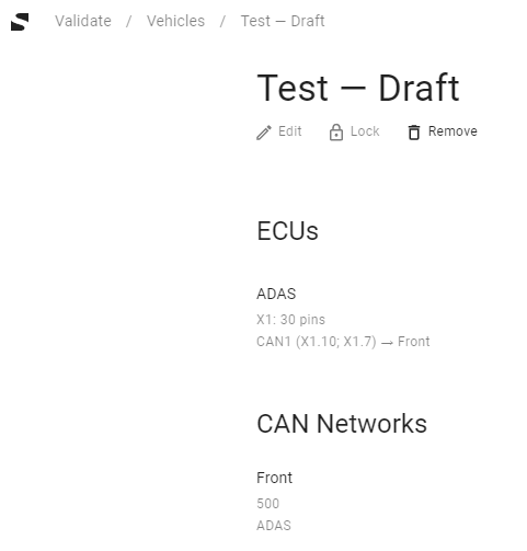
Once the vehicle is locked, you can add “Builds” and “Simulation Models Configurations” to finalize the setup.

1.4.3. Simulation Models Configurations
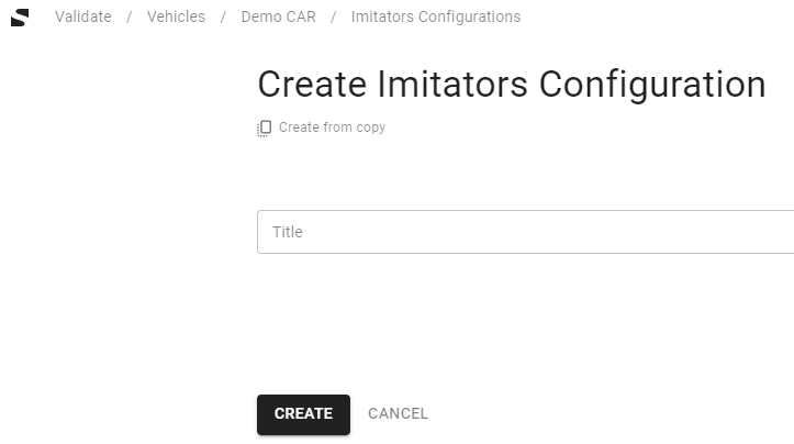
In Validate Studio, the “Simulation Models Configurations” section is designated for setting up simulators that emulate vehicle behavior.
Begin by naming your configuration and generating an instance.
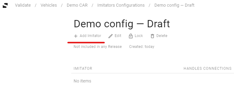
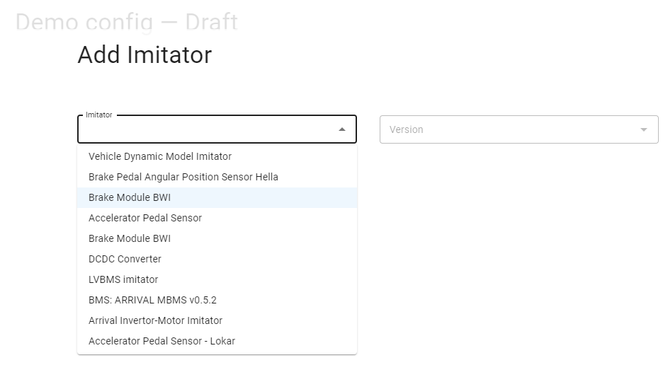
Then, proceed to incorporate simulation models and their specific versions, which you have previously uploaded, into this configuration. These steps are crucial for tailoring the simulation environment to the characteristics of the vehicle being modeled.
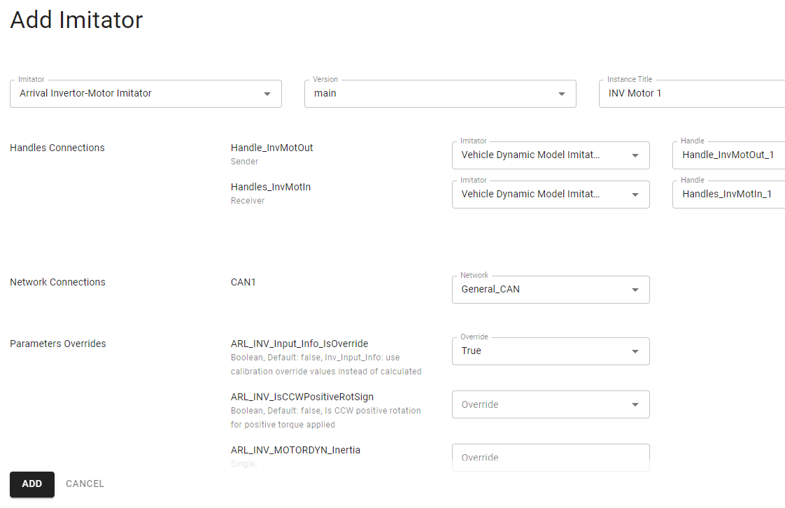
Once you have added an simulation model in Validate Studio, you can fine-tune its settings to match your specific vehicle requirements. This includes:
connecting CAN ports and pins to the vehicle’s networks and ECUs,
adjusting simulation model parameters, and
defining the communication handles for data exchange between different simulation models.
After customizing the simulation model to your satisfaction, you have the option to lock the configuration for future use, or you may choose to edit or remove the simulation model if further adjustments are needed.
1.4.4. Builds
In Validate Studio’s “Builds” section, you can generate a new build for vehicle testing.
To do this, press “+ Create New Build” and fill in details such as the build version and the software versions for each ECU.
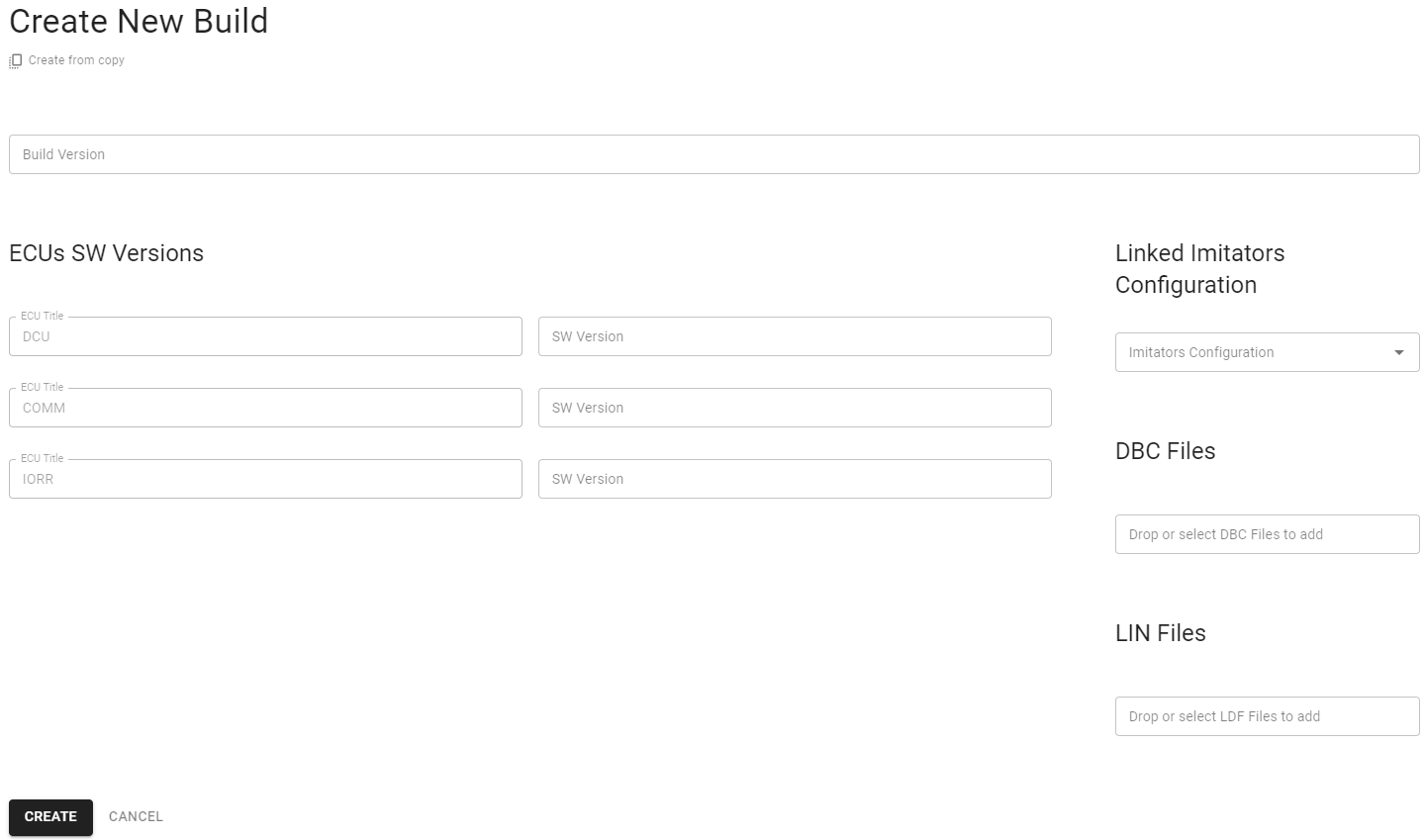
Determine the version for your new build, which can be any combination of letters and numbers of your choosing.
Then, for each ECU, specify the software version. You can also upload dbc files and link the necessary Simulation Models Configuration for the vehicle.
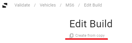
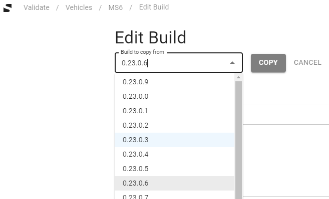
If needed, you can base a new build on an existing one by using the “Create from copy” function, allowing you to carry over settings from a previous setup.
This feature streamlines the process of managing and updating vehicle builds for continuous integration and testing.
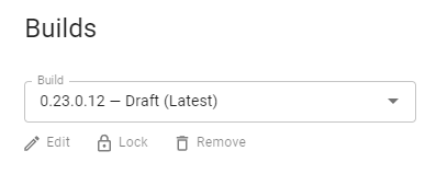
Upon the completion of a build, Validate Studio presents you with several management tools on the vehicle’s page, allowing you to modify (Edit), finalize (Lock) for upcoming testing, or eliminate (Remove) the build as needed.
These options offer flexibility in managing the lifecycle of each build you create.
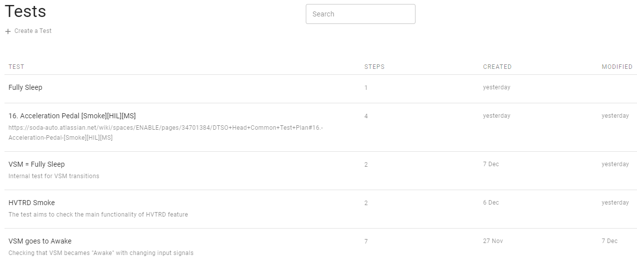
1.5. Tests Library
1.5.1. Tests
The “Tests Library” in Validate Studio comprises:
A button to create new tests.
A search function to find tests by name.
A display of all tests with options to view their details and implementations.
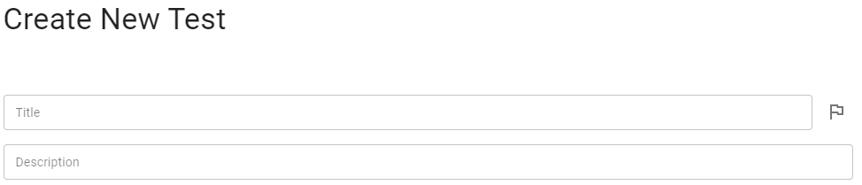
To begin creating a test, select the “Create a Test” button.
Enter a unique name for the test and provide a description if necessary.
Use the flag option next to the test name to prioritize the test or note it as unreliable.
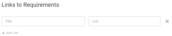
Link your test to related requirements to assist with tracking test coverage and traceability.
Link the test with requirements to have the ability to calculate your test coverage, control traceability, and have a fast way to go to the source of expectation.
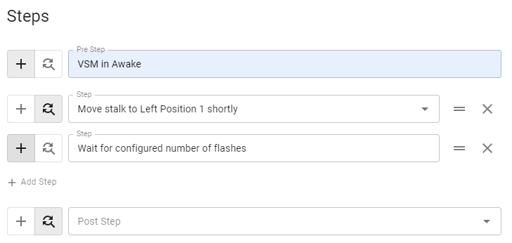
Just write the new step’s name to create a new test step.
Or you can reuse existing steps by selecting a searching button and choosing a step from the list.
Using “Pre Step” and “Post Step” is optional.
You can reorder test steps or delete them with corresponding controls on the right side of the screen.
After test creation, you can see the window with a proposal to write an implementation of test steps.
Select the vehicle and the build to get information about the implementation of this test for this environment. The orange mark near the name of the test indicates that there is at least one step without an implementation for the selected vehicle and build.
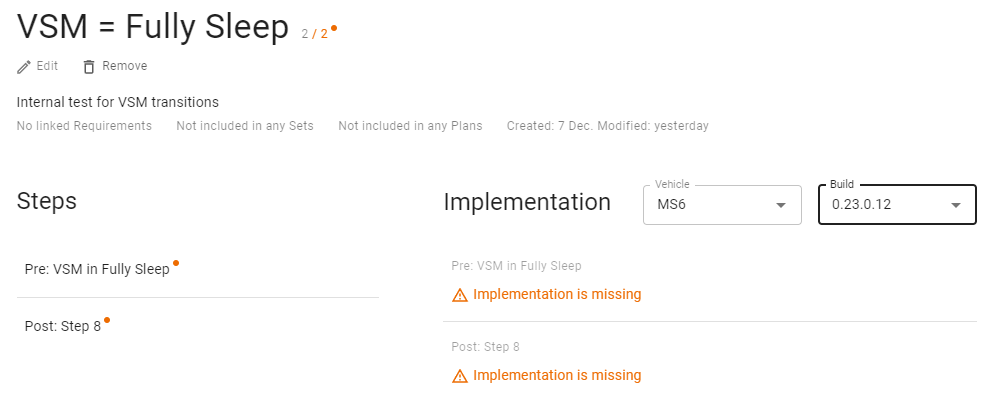
Click on the step name to open the Implementations of this step
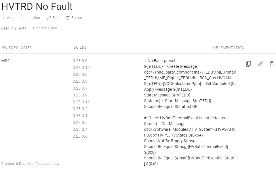
You can add new implementations from scratch or copy from presented ones, edit, or delete them.
The Edit Implementation window allows code implementation and links it to specified vehicles and builds:
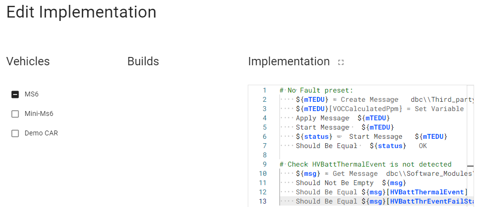
Use our SODA Keywords Guide for more information about coding test steps.
Built-in Robot Framework keywords - official documentation.
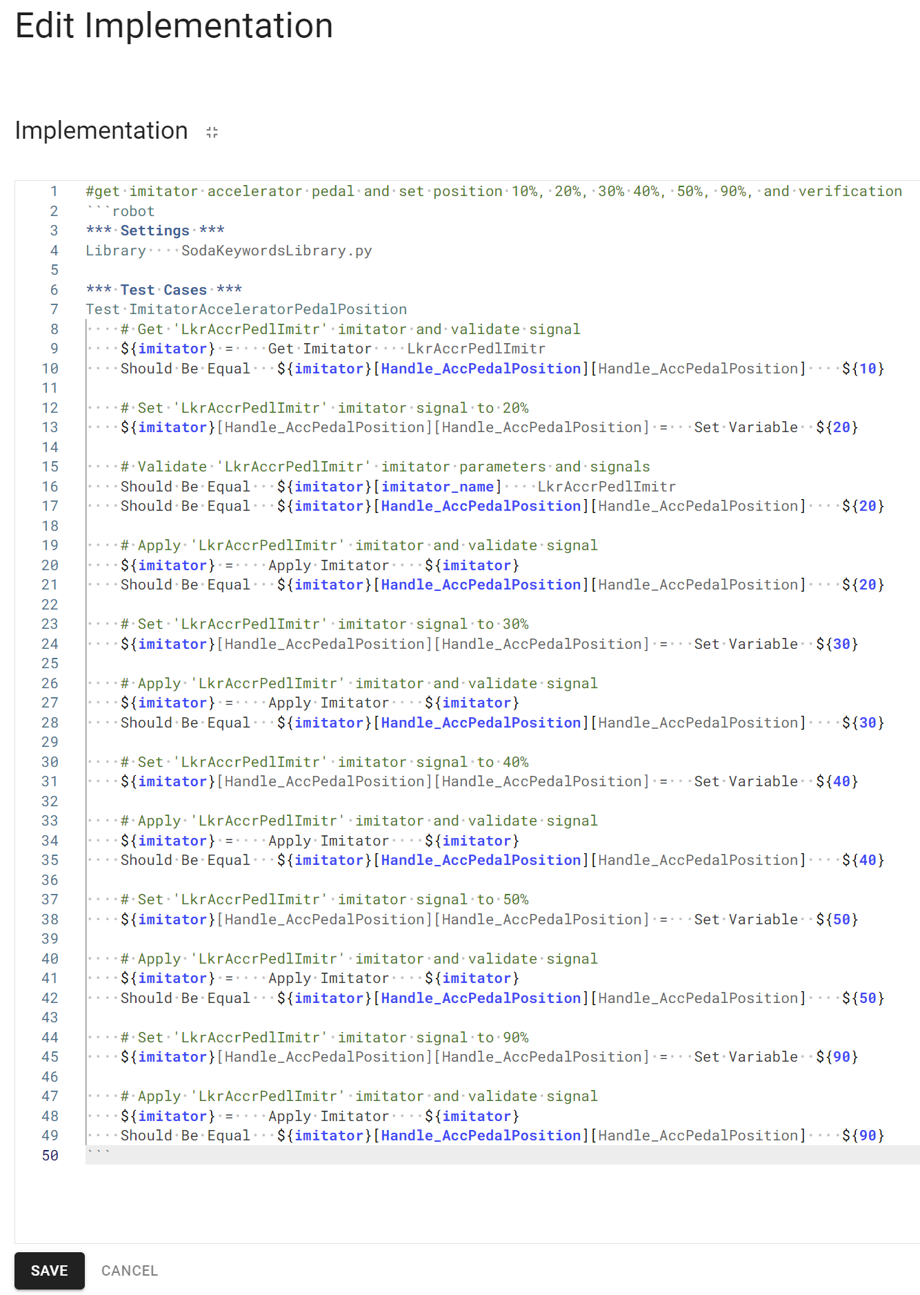
Or use Co-Pilot. Write a human-readable request, click ctrl+L, and check the generated code. For example: #get simulation model accelerator pedal and set position 10%, 20%, 30% 40%, 50%, 90%, and verification
1.5.2. Sets
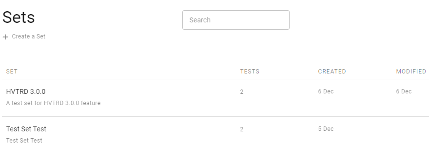
Test Sets allow you to group several tests by any criterion, for example, by feature or hardware domain. All tests where the Human-Machine Interface (HMI) is used can be grouped into the Test Set: “HMI-related tests.”
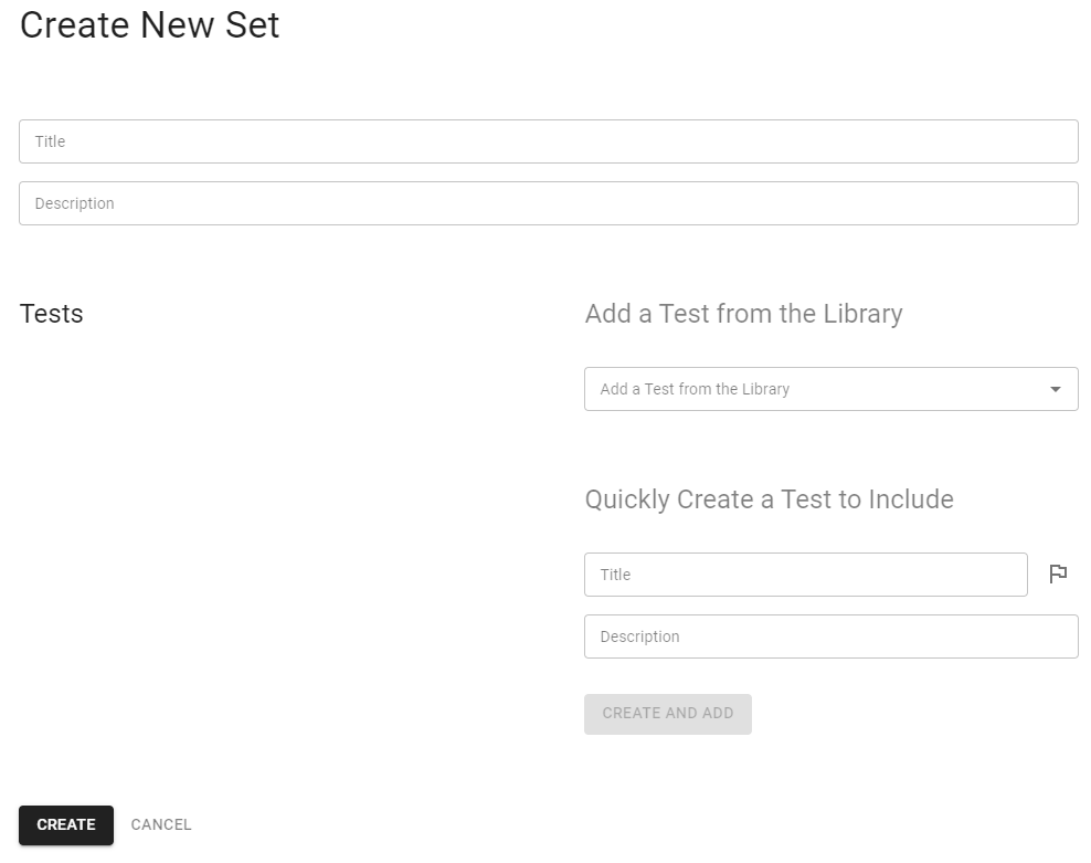
Click the “Create a Set” button to create a new set.
The “Create New Set” window allows you to name new sets, add existing tests, or quickly create a new test with a connection to the new set.
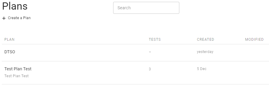
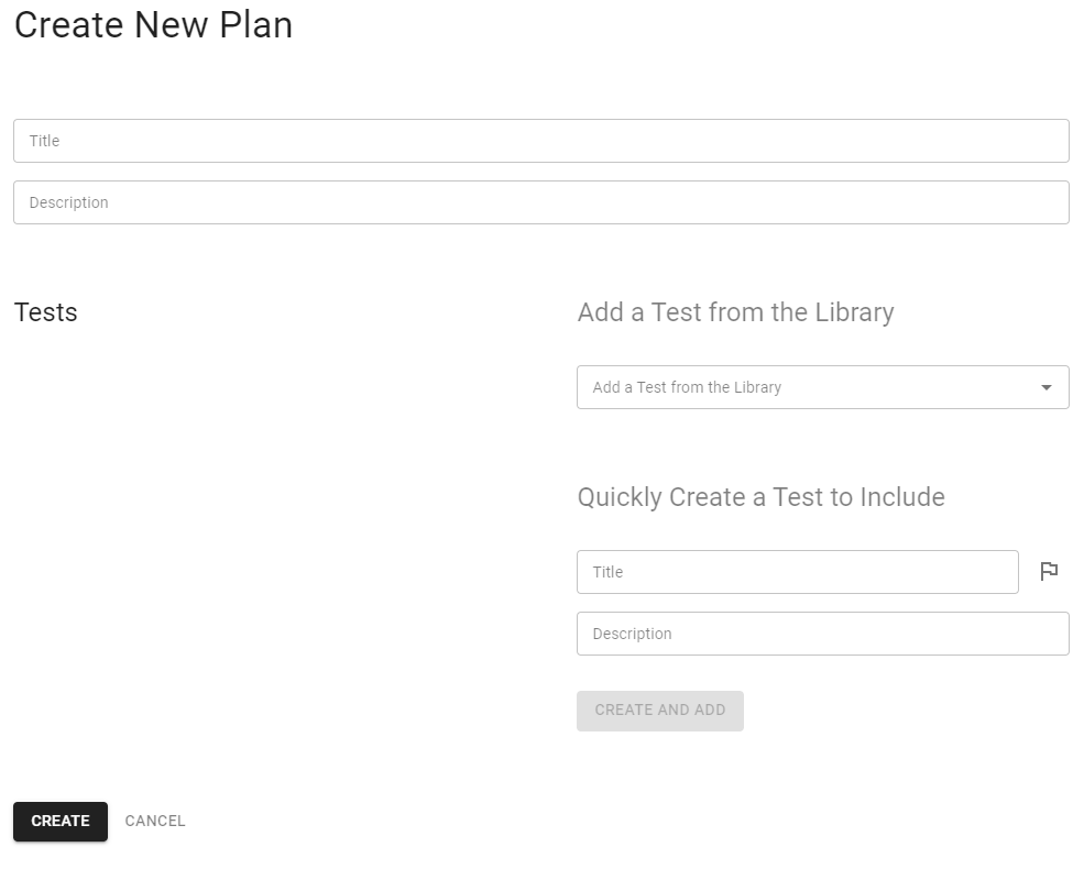
1.5.3. Plans
Test Plans can contain separate tests and test sets. Test Plans are used when the whole release is planned to be tested. For instance, next-release testing should include new features tests, Regression tests, and a few performance tests.
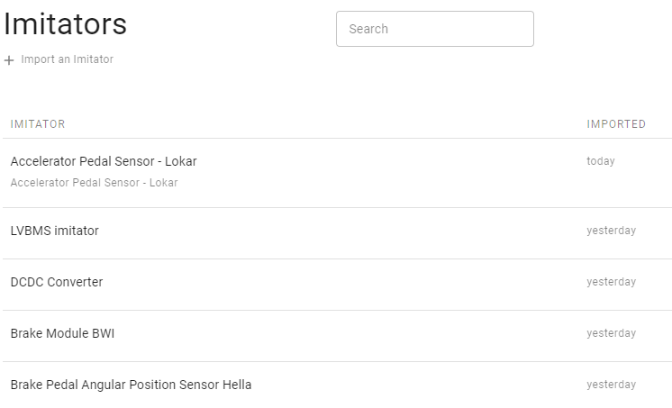
1.6. Simulation Models
The Simulation Models window contains three basic elements:
The “Import an Simulation Model” button
The search field to find Simulation Models by name
The list of all Simulation Models from where you can go to their description and implementations
To create a new Simulation Model, push the according button at the top of the window.
There are fields to upload the simulation model’s XML, DLL, and dbc files here.
After uploading, they can be used in Simulation Model configurations.
1.7. Rigs
The Rigs page contains the list of all Rigs from where you can go to their description.
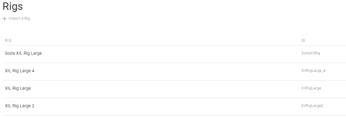
From the main page of Rigs, you can also go to the page of importing XML files of the stand to create a new Rig. XML contains basic information about the Rig’s hardware.
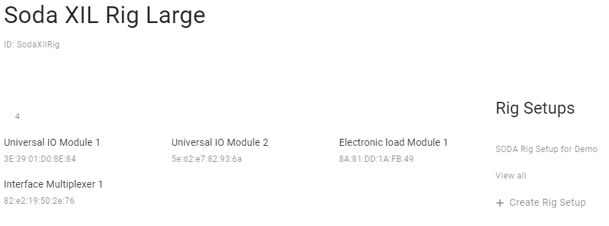
To configure connections between a Rig and your ECUs, it is necessary to create a Rig Setup.
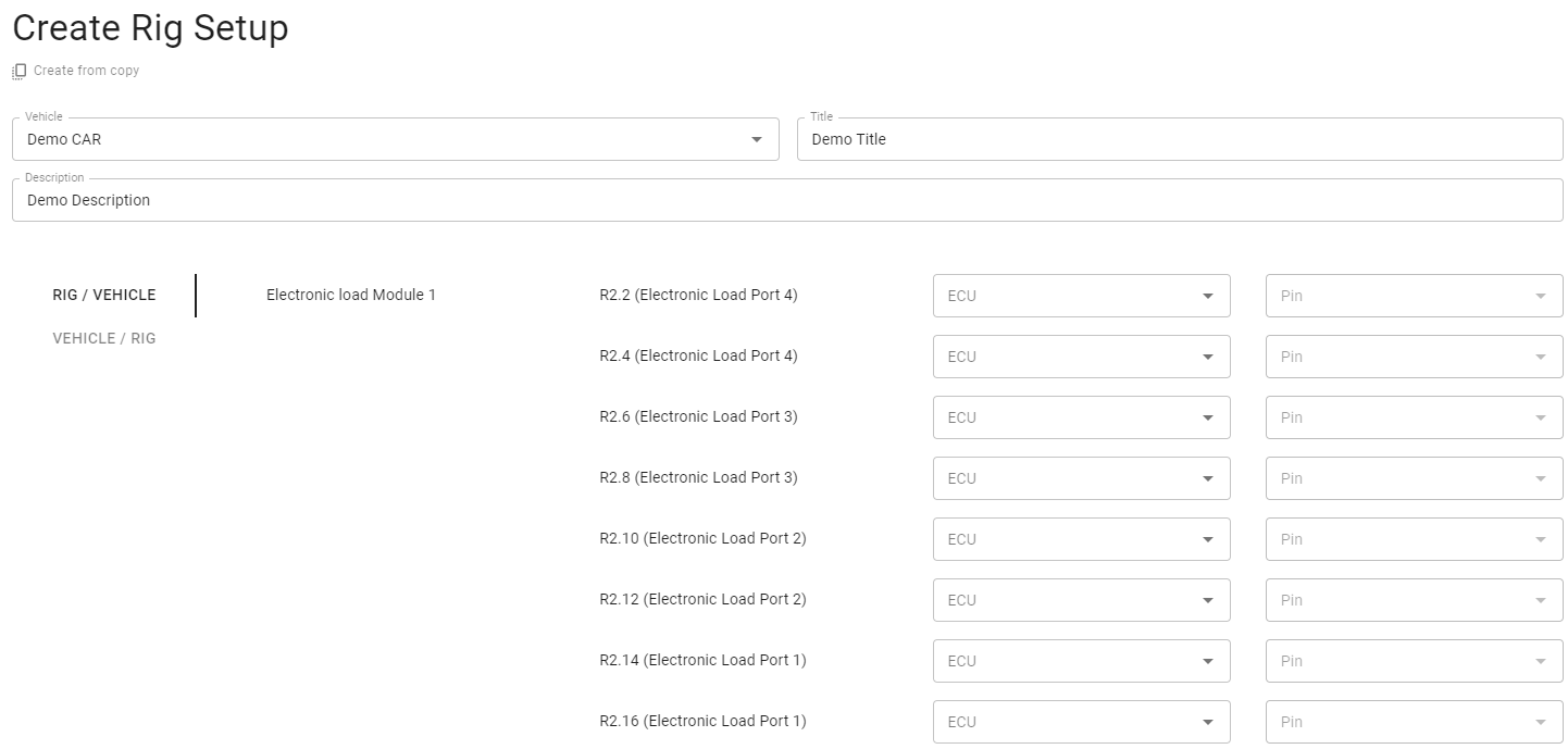
Select a Vehicle and optionally specify a Title and a Description.
Match the virtual schema on the page with the real connections.
There are two options for what to have as a base element: RIG modules or Vehicle ECUs.
You can select the preferable mode in this section:

1.8. Executions
On the Executions page, you can find the list of executions with their statuses and create a new one:
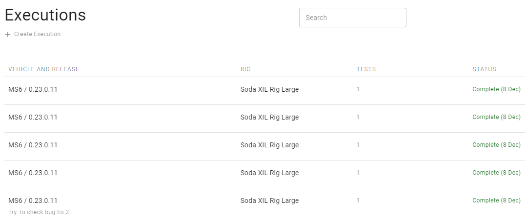
To create a new Execution, press the corresponding button.
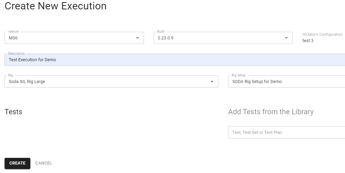
On the opened page, specify the environment for your tests:
Vehicle
Build
Description (not necessary)
Rig
Rig Setup
Tests
Tests can be selected separately by name, by Test Set, or by Test Plan.
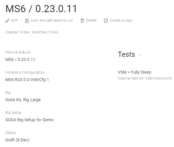
After adding all necessary information, save this information as a draft by clicking on the “Create” button.
If all test step implementations exist for the selected vehicle and build, there is an active button “Lock and get ready to run” that makes it possible for the Execution to run.
Also, you can edit and delete this draft or create a copy from this Execution.
To run the execution after locking, click on the button “Run on Rig [name of your Rig]”.
After that, the status is changed to “In progress”.
After the end of the execution, the status will be changed to “Complete”.
The log of the execution will be attached below.
In case when the Rig is busy with another task, you will see the corresponding message:
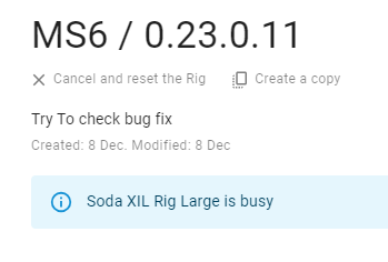
Just wait for a while or cancel the execution.