3. Software-Defined Rig
3.1. Introduction
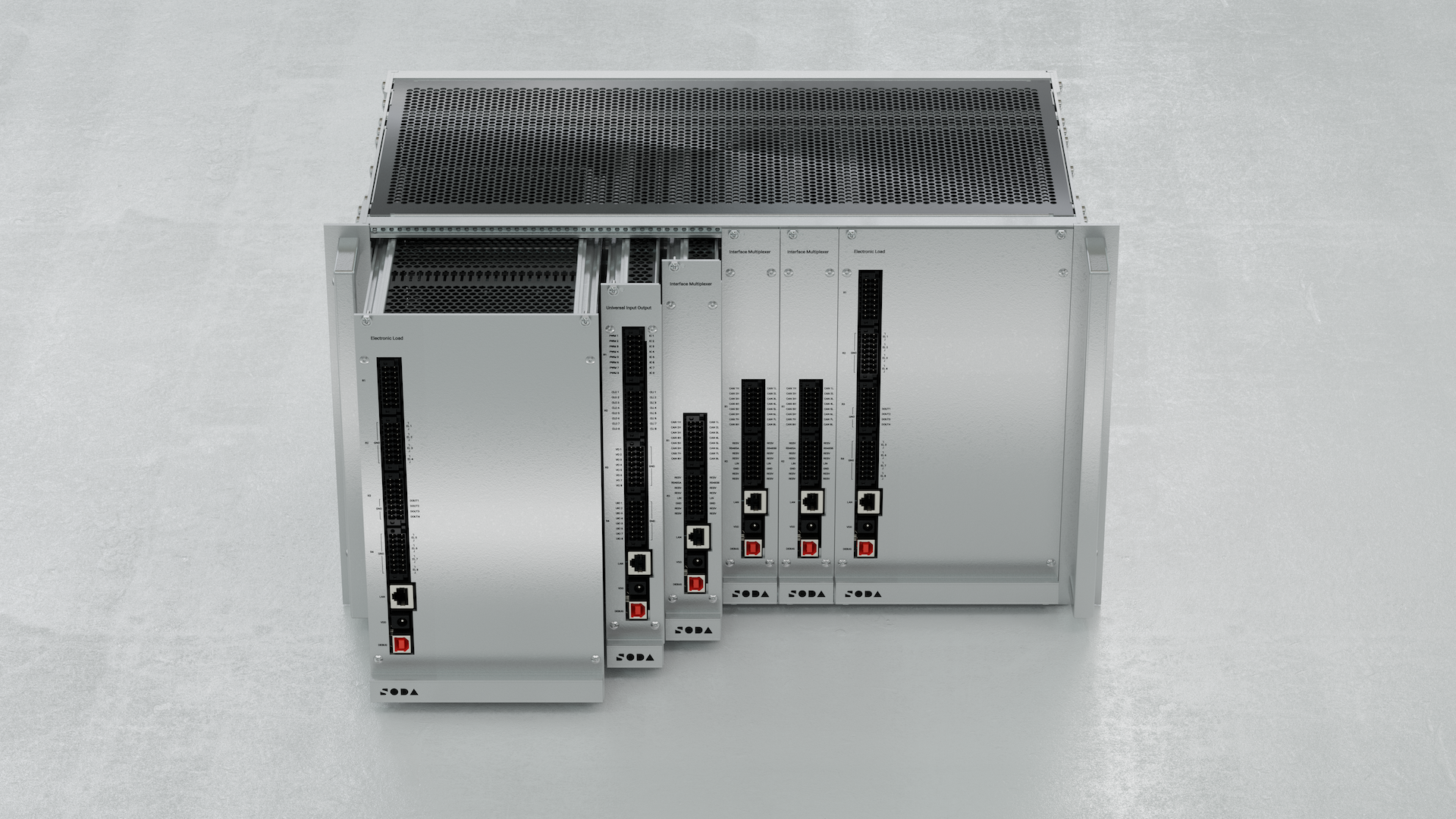
The Software-Defined Rig (SDRig) is a modular, rack-mounted testing platform tailored for automotive HIL simulations. Modules include:
Interface Multiplexer (MUX) for network simulation (CAN, LIN)
Universal Input / Output (UIO) for analog/digital signal simulation
Electronic Load Module (ELM) for actuator/load emulation
Each module can operate in the rig or standalone over 100Base-T Ethernet. The system supports power distribution and flexible signal routing through a backplane PCB.
3.2. Modules at a glance
MUX — 8× CAN FD channels (up to 5 Mbps, 8 external + 16 backplane), 1× LIN 2.0; electromagnetic relay matrix for interaces routing; 100Base‑T Ethernet.
UIO — 8× universal channels: voltage in/out (0–24 V), PWM in/out (20 Hz–5 kHz), current loop Tx/Rx (0–20 mA); high‑accuracy signal simulation; Ethernet.
ELM — 8× universal load channels (current sink 0–10 A @ 0–24 V), voltage in/out 0–24 V; 4× 24 V relay sourcing; up to 200 W/channel, 600 W total; Ethernet.
3.3. Compliance
All modules are compliant with:
RoHS Directive 2011/65/EU + 2015/863/EU
WEEE Directive 2012/19/EU
3.4. Interface Multiplexer Module (MUX)
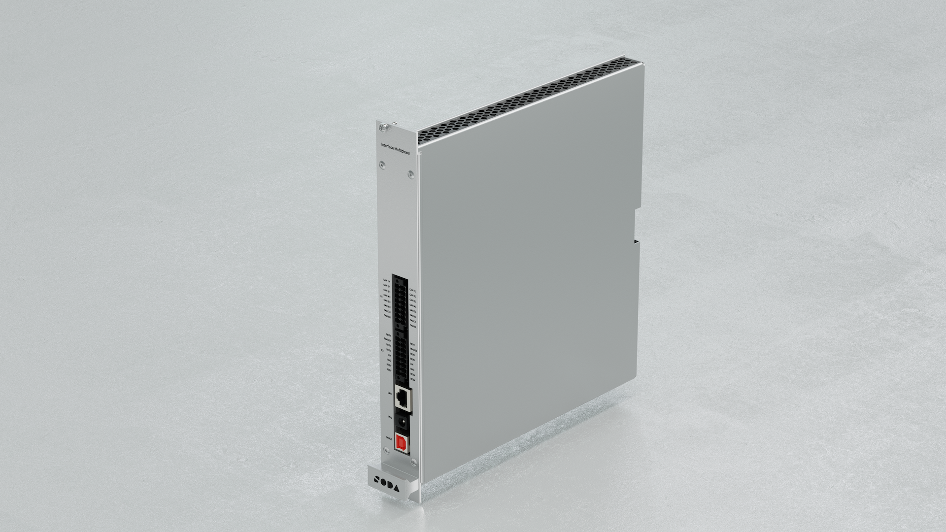
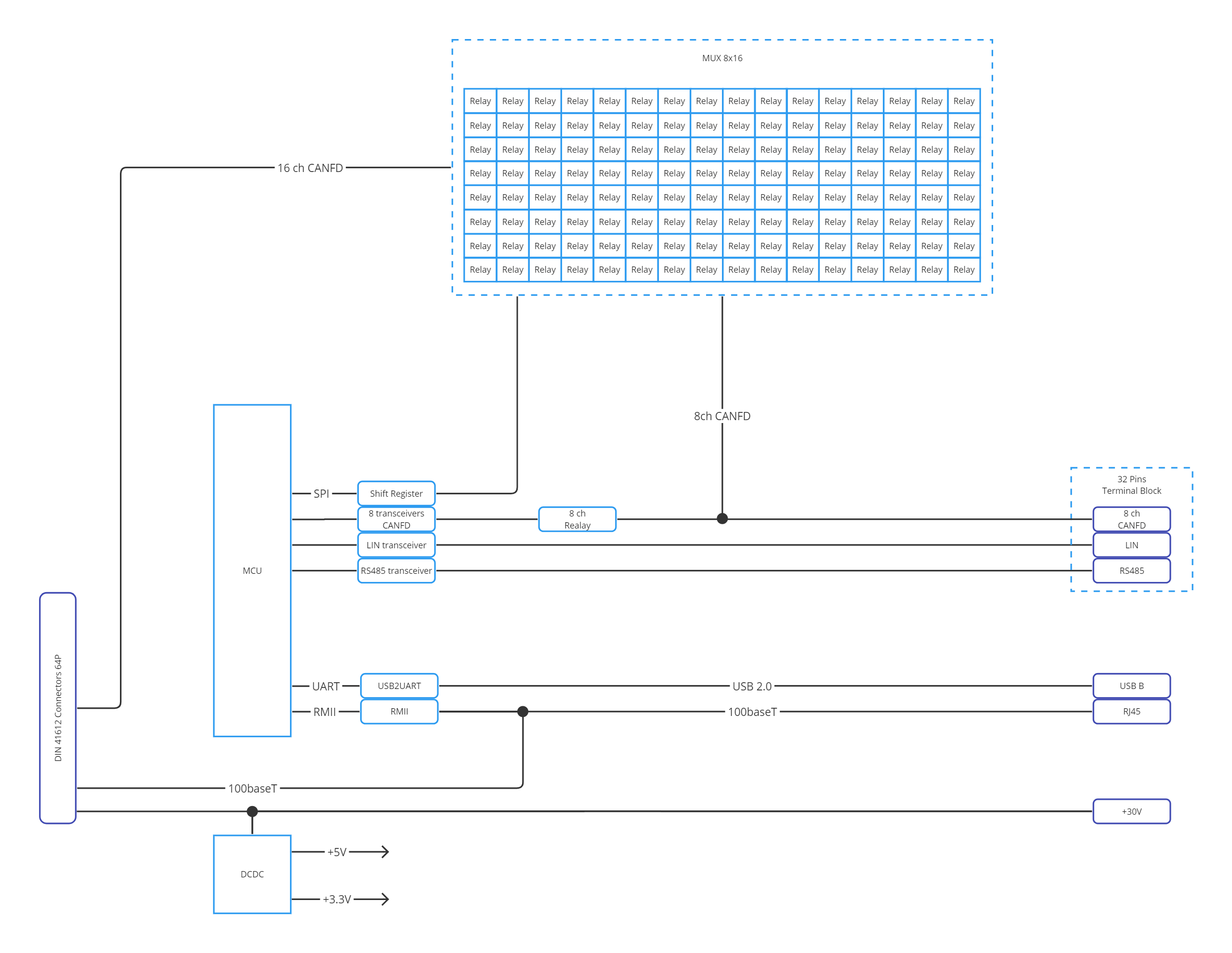
The Interface Multiplexer is a module designed for simulating vehicle networks and peripheral devices connected to Electronic Control Units (ECUs) through digital interfaces. Its primary feature is the CAN FD multiplexer, implemented as a matrix of electromagnetic relays, capable of connecting any CAN ECU to the CAN rig.
3.5. Features
8× Universal CAN FD Channels (up to 5 Mbps, 8 external + 16 backplane)
1× LIN 2.0 channel
Electromagnetic relay matrix for routing
Ethernet 100Base‑T interface
3.6. Specifications
Dimensions: 245 × 260 × 36 mm
Weight: 1010 g
Voltage Supply: 26–28 V DC
Supply Current: 0.3 A
Nominal Power Consumption: 2.5 W
Startup Power: 4.8 W
Operating: 0–50°C, ≤80% RH @35°C
Storage: −40 to +70°C
Warm‑up: 30 min
3.7. Functional diagram
3.8. Connectors
3.8.1. R1 – CAN Channels
Pin |
Signal |
Description |
|---|---|---|
R1.1–R1.16 |
CANxH/L |
8× CAN FD H/L pairs |
3.8.2. R2
Pin |
Signal |
Description |
|---|---|---|
R2.8 |
LIN |
LIN 2.0 (slave only) |
R2.2 |
24V |
Power supply |
R2.3 |
GND |
Ground |
3.8.3. LAN / VDD / DEBUG
LAN: 100Base‑T Ethernet
VDD: 30 V DC input for standalone mode
DEBUG: Reserved for calibration
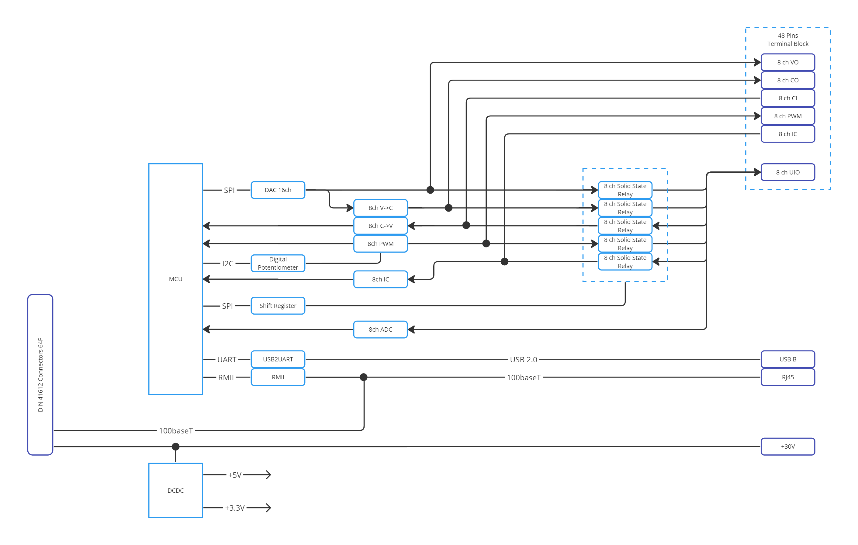
3.9. Universal Input / Output Module (UIO)
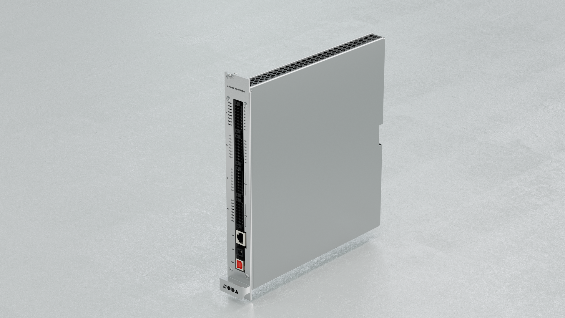
The Universal Input / Output is a module designed for simulating analog vehicle sensors. Its primary feature is the universal pin, capable of setting/measuring voltage, generating PWM, input capture, and being a current loop transmitter and receiver.
3.10. Features
8× Universal I/O Channels:
Voltage measurement/setting: 0–24 V
PWM Input/Output: 20 Hz – 5 kHz
Current loop Tx/Rx: 0–20 mA
High accuracy signal simulation
Ethernet interface
3.11. Specifications
Dimensions: 245 × 260 × 36 mm
Weight: 940 g
Voltage Supply: 26–28 V DC
Supply Current: 0.3 A
Power Consumption: 2.5 W nominal / 4.8 W startup
Operating: 0–50°C, ≤80% RH @35°C
Storage: −40 to +70°C
Warm‑up: 30 min
3.11.1. Channel Performance
Voltage In: 0–24 V
±20 mV [0–2 V], ±1% [2–24 V]
Processing time: 10 ms
Voltage Out: 0–24 V
±20 mV [0–2 V], ±2% [2–24 V]
Settle time: 10 ms
Current Loop In/Out: 0–20 mA
±1% accuracy, 20 ms settle time
PWM / ICU:
Frequency: 20 Hz – 5 kHz
Accuracy: ±1% (freq), ±1–2% (duty)
Voltage: 5 V ± 100 mV
Settle time: 250 ms
3.12. Functional diagram
3.13. Connectors
3.13.1. R4 – Universal I/O
Pin |
Signal |
Description |
|---|---|---|
R4.1 |
UIO8 |
Voltage/PWM/Current Loop (all modes) |
R4.3 |
UIO7 |
Same as UIO8 |
R4.5 |
UIO6 |
Same as UIO8 |
R4.7 |
UIO5 |
Same as UIO8 |
R4.9 |
UIO4 |
Same as UIO8 |
R4.11 |
UIO3 |
Same as UIO8 |
R4.13 |
UIO2 |
Same as UIO8 |
R4.15 |
UIO1 |
Same as UIO8 |
R4.2, R4.4, …, R4.16 |
GND |
Ground |
3.13.2. LAN / VDD / DEBUG
LAN: 100Base‑T Ethernet
VDD: 30 V DC input
DEBUG: Reserved for calibration
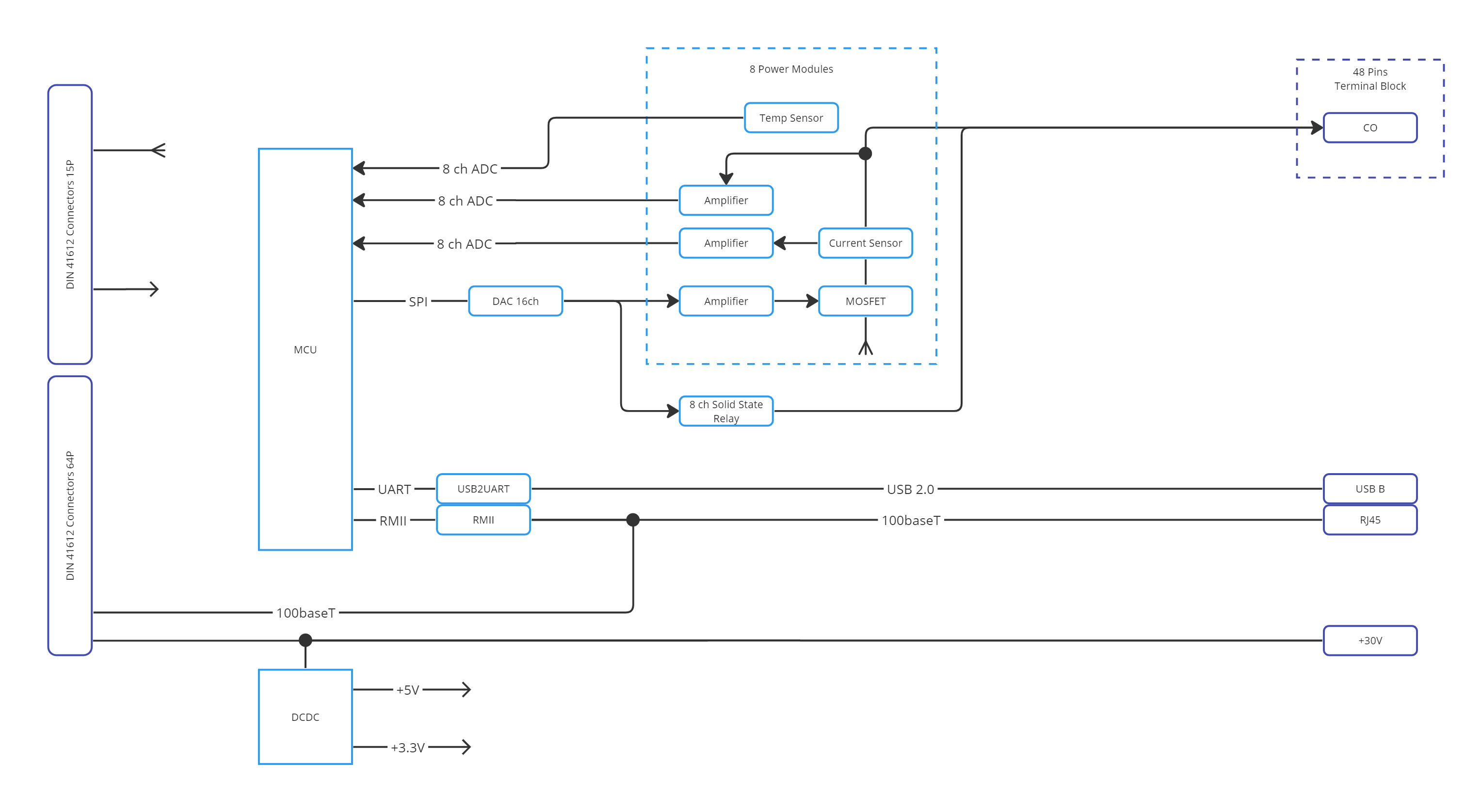
3.14. Electronic Load Module (ELM)
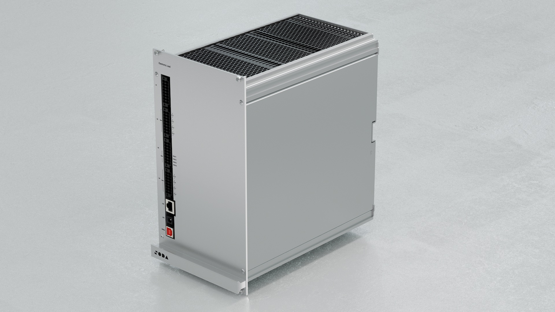
The Electronic Load module is designed for simulating analog vehicle actuators and loads of ECU. Its primary feature is the MOSFET module, capable of dissipating up to 200 W on each channel and up to 600 W on all channels.
3.15. Features
8× Universal Load Channels:
Current sinking: 0–10 A @ 0–24 V
Voltage measurement/setting: 0–24 V
4× Relay sourcing channels (24 V / 100 mA)
Max: 200 W/channel, 600 W total
Ethernet interface
3.16. Specifications
Dimensions: 245 × 260 × 144 mm
Weight: 5250 g
Voltage Supply: 26–28 V DC
Supply Current: 0.3 A
Nominal Power Consumption: 2.5 W
Startup Power: 4.8 W
Thermal Limit: 200 W/channel, 600 W total
Operating: 0–50°C, ≤80% RH @35°C
Storage: −40 to +70°C
Warm‑up: 30 min
3.16.1. Channel Performance
Voltage In: ±20 mV [0–2 V], ±1% [2–24 V]
Voltage Out: ±20 mV [0–2 V], ±2% [2–24 V]
Current In: ±5%, range 0.1–10 A
Response Time: Voltage 10 ms, Current 20 ms
3.17. Functional diagram
3.18. Connectors
3.18.1. R2 – Load Channels 1–4
Pin |
Signal |
Description |
|---|---|---|
R2.16–R2.14 |
EL1–EL4 |
Universal Load Channels |
others |
GND |
Ground |
3.18.2. R3 – Relay Sourcing
Pin |
Signal |
Description |
|---|---|---|
R3.12–R3.6 |
DOUT1–DOUT4 |
24 V sourcing (relay) |
R3.1–R3.3 |
24 V |
Source voltage |
R3.11 |
GND |
Ground |
3.18.3. R4 – Load Channels 5–8
Pin |
Signal |
Description |
|---|---|---|
R4.16–R4.14 |
EL5–EL8 |
Universal Load Channels |
others |
GND |
Ground |
3.18.4. LAN / VDD / DEBUG
LAN: 100Base‑T Ethernet
VDD: 30 V DC input
DEBUG: Reserved for calibration
3.19. Compliance
All modules are compliant with:
RoHS Directive 2011/65/EU + 2015/863/EU
WEEE Directive 2012/19/EU
Disposal & Recycling: do not discard with general waste. Use certified recycling services.
3.20. Working with SODA Validate Studio
SDRig is pre‑integrated with SODA Validate Studio for lab‑friendly, role‑based testing:
Create and edit test environments (signal maps, routing, datasets).
Author tests with the AI assistant and organize suites.
Run executions on the rig (single or multiple VLAN‑bound instances).
Browse and download reports and logs.
Documentation: See the SODA Validate Studio docs → Validate Studio
3.21. Programmatic control via SDK
You can control SDRig directly from your own tools and CI pipelines using our SDKs:
C++ SDK: https://github.com/soda-auto/soda-validate-sdrig-sdk-cpp — build with CMake; see the repository README for targets and examples.
Python SDK: https://github.com/soda-auto/soda-validate-sdrig-sdk-py — use in virtualenvs or docker; see the repository README for usage and examples.